Effect of surface hardening by high frequency induction heating
2006/3/28 Views
Surface hardening of carbon steel by high frequency induction heating (HFIH) produces a considerable increase in its resistance to stress corrosion [1, 2]. The magnitude of this increase depends on the depth of surface hardening, on the strength of the specimen core, and on other factors whose influence was studied in this investigation.
effect of surface hardening
The surface hardening of steel 40Kh specimens was done
by
heating them continuously and progressively in a single-coil
inductor of a HF
induction set LGPZ-60 (frequency = 200-300 kc,
power rating = 60 KW). The
initial structural state of the specimens
varied: some had a
pearlito-ferritic structure (produced by
annealing) while some consisted of
martensite, troostite or sotbite
(produced by quenching the specimens from
880~ and tempering
them for 2 hr at 180, 850, or 800~ respectively).
The
depth of the surface-hardened layer was 0.8, 1.8 mm in
martensitic
specimens, 1.2 and 1.8 mm in specimens consisting
of
troostite, and 1.4 and 1.8 mm in the case of specimens with a
sorbitic
structure. The depth of surface hardening was uniform
in both the radial and
axial directions. After the surface hardening,
the specimens were tempered (2
hr at 180~ and ground to
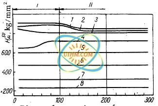
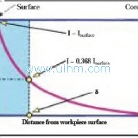
a Class 8 surface finish. The hardness of
surface-hardened layer
was HRC = 55-57; the variation in the microhardness
with the
distance from the specimen surface is shown in Fig.
1.
Stress-corrosion tests were carried out on cylindrical specimens
(20 mm
diam. ) stressed in tension in a 20% I12SO4 solution
at room
temperature.
The results showed that the stress-corrosion resistance
of
steel with tile initial pearlito-ferritic structure is substantially
higher after surface hardening than after ordinary quenchhardening
(Fig. 2,
curves 1,4, 5, G).
Increasing the surface-hardening depth from 0.8 to 2. ,5
mm produces a dight increase in the conditional static
corrosion-fatigue
limit (stress-to-rapture). The optimum surface-hardening depth for steel with an
initial pearlito-ferritic structure is 1.8 mm. A larger increase in the
conditional static corrosion-fatigue limit is produced by surface hardening of
specimens with a harder (in comparison with pearlito-ferritic) core. And so,
surface hardening by HFIH produced a 2.5-2.8 increase in the conditional static
corrosion-fatigue limit of specimens which initially had a martensitic,
troostitic or sorbitic structure (see Fig. 2), the optimum surface-hardening
depth being 0.6, 1.2 and 1.4 mm, respectively.
Although the stress-corrosion
resistance of steel after surface hardening is usually higher than after
ordinary quenchhardening, the latter treatment followed by tempering at 550 ~ C
ensures a much higher resistance to stress corrosion
(Fig..q). Consequently,
the surface hardening by tlFItt may be recommended as a means of improving the
stress-corrosion
resistance of parts working under conditions that require a
high surface hardness.
Data plotted for specimens with different structures
surface-hardened to the same depth (Fig. 3, curve 2) or to
tile optimum depth
for a given structure (Fig. 3, curve shows that in both cases the maximum value
of the conditional
static corrosion-fatigue limit after surface hardening by
ttFItt was recorded for steel with a troostitic structure and the
lowest for
specimens with a pearlito-ferritic structure.
The differences in the
stress-corrosion resistance of steel given a surface-hardening treatment are
associated with differences in the structure of the material and in the
magnitude of residual stresses produced in the metal surface layers
(Fig. 4)~
Surface hardening by HFIH of specimens with an initial pearlito-ferritie,
troostitic or martensitic structure produced surface layers consisting of two
zones (I, II) possessing different microhardness (Fig. 1) and structure.
Fig. 2. Stress-corrosion curves of steel 40Kh specimens after the
following
heat treatments: 1, 2, 18) ordinary quench-hardening followed by
tempering
at 180, 850, and 550~ respectively; 3,4) surface hardening of steel
with
a pearlito-ferritic structure by HFIH to a depth of 0.8 ram, curves 8
and 4
relating to specimens with one and several surface cracks,
respectively; 5,
6) surface hardening of steel with a pearlito-ferritic
structure by HFIH to a
depth of 2.5 and 1.8 mm, respectively; 7, 10) surface
hardening of steel
with a sorbitic structure to a depth of 1.8 and 1.4 mm,
respectively; 8, 11)
surface hardening of steel with a martensitic structure
to a depth of 1.8 and
0.6 mm, respectively; 9, 12) surface hardening of steel
with a troostitic
structure to a depth of 1.8 and 1.2 mm, respectively.
The microstructure of the surface layer of steel with an initial
pearlito-ferritic structure is characterized after surface
hardening by a
highly dispersed martensitic structure and a high microhardness (Fig. 1, curves
1, 5); a certain reduction
in microhardness observed in zone II is
attributable to a larger grain size.
In the case of specimens with an initial
troostitic structure, surface hardening led to the formation of surface
layers
consisting of acicular martensite with an increased troostite content
and having, as a result, a slightly lower microhardness
(Fig. 1, curve 4,
zone I); this zone changes gradually to finely dispersed martensite with a
higher microhardness
(Fig. 1, curve 4, zone II).
Surface hardening of specimens with an initial martensitic structure produces surface layers which
consist of finely
dispersed martensite changing to a more
coarsely-crystalline martensite with small troostite regions; the maximum
microhardness
is observed in zone I (Fig. 1, curve 2).
*The determination
of residual axial stresses was done by measuring the strain of specimens from
which successive
surface layers were removed by dissolution [3].
Fig. 4. Distribution of residual stresses after surface hardening by HFIH
of
steel specimens with a pearlito-ferritie structure to a depth of 0.8 and
1.8
mm (curves 1 and 4, respectively), with a sorbitic structure to a depth
of
l. 4 mm (curve 2), and with a martensitic structure to a depth of 0.6
mm
(curve 8).
And so, rapid HFIH during surface hardening of steel
specimens with various initial structures leads in every case
to a refinement
of the crystal structure and to an increase in microhardness. As a result,
residual compressive stresses
are produced in metal surface layers; their
extent and distribution depend on the depth of surface hardening, heating and
cooling rates, changes in the specific metal volumes and other factors.
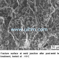
Fig. 8. The appearance of fracture surfaces of surface-hardened
specmens
of steel 40Kh with the following initial structures: a, b)
pearlitoferritic;
c) troostitic; d) martensitic.
When surface-hardened
specimens of steel with an initial pearlito-ferritic structure are
stress-corrosion tested,
numerous closely situated cracks are formed on their
surface; due to the self-relieving effect [5] these cracks produce
a smaller
reduction in the conditional static corrosion-fatigue limit than that produced
by a single crack* (Fig. 2,
curves 8, 4).
The fracture surface of these
specimens is clearly divided into two zones: a zone of the propagation of a
corrosion
crack through the surface-hardened layer, and the zone of ultimate
fracture in the specimen core (Fig. 8a). In isolated
cases a brittle fracture
took place as a result of simultaneous propagation of several cracks, as a
result of which a steplike
fracture surface was produced (Fig. 5b).
In the
case of surface-hardened specimens with initial sorbitic, troostitic (Fig. 5c)
and martensitie (Fig. 8d) structures,
the fracture took place along the path
of the first crack formed; metallographic examination revealed no
other
cracks in specimens of this kind.
*The formation of a single crack
was ensured by painting the specimen gauge portion with a bakelite varnish
and
then making a circular incision in the varnish coating to expose a very
narrow band of specimen surface.
REFERENCES
1. V.T. Stepurenko, Investigation of the Corrosion and
Stress-Corrosion Resistance of Steel St. 45 [in Russian],
Izd. AN USSR,
L’vov, 1958.
2. I.I. Vasilenko et al., FKhMM [Soviet Materials Science], no
2, 227, 1966.
3. C.V. Karpenko and B.F. Ryabov, et aL, FKhMM [Soviet
Materials Science], no I, 1966.
4. G.V. Karpenko, Strength of Steel in
Corrosive Media [in Russian], Mashgiz, 1963.
20 September 1967 Institute of
Physics and Mechanics, AS UkrSSR, L’vov
Down Attachment
- DownloadAttach1: effect-of-surface-hardening-by-high-frequency-induction-heating.pdf Clicks
Related Download

parallel resonance circuit of 15KW to 110kw medium frequency induction heater

How to design induction coils yourself(DIY)
Induction welding steel pipes
what is Furnace Brazing

induction heating for cars overview of applied automotive applications
Induction Heating of Flat Objects
hardening induction coil

Solid State Technology of Induction Heating


Newest Comment
No Comment
Post Comment